Leviton Ceiling Occupancy Sensor Wiring Diagram
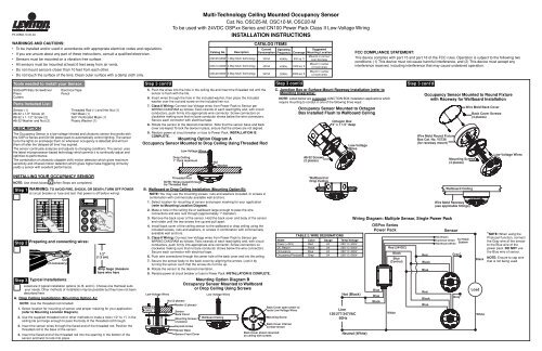
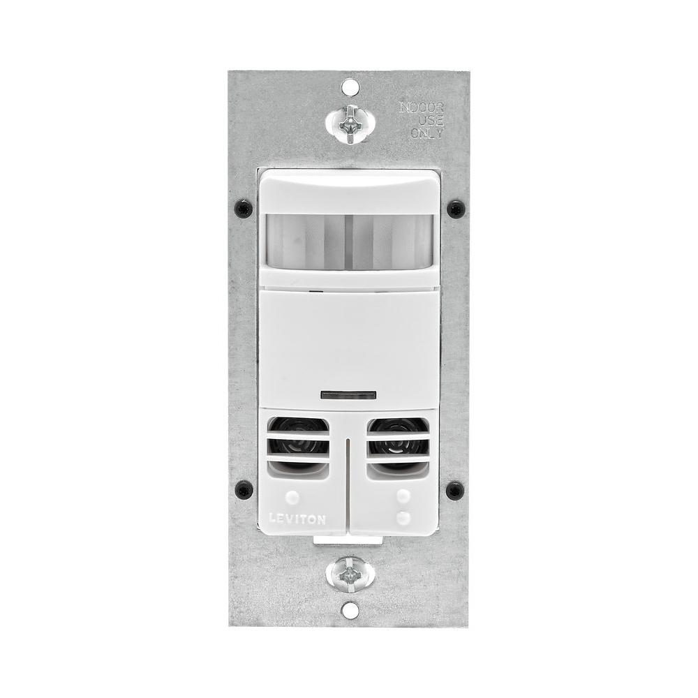
Multi Technology Ceiling Mounted Occupancy Sensor Leviton

Zenith Motion Sensor Wiring Diagram Is One Example Of A Occupancy Motion Sensor Switch Wiring Diagram Sensor Bath Exhaust Fan Diagram

Leviton Presents How To Install The Ipv15 Ips15 Universal Occupancy And Vacancy Sensor Youtube
Lv O3c15 Idw Leviton Odc Pir Ceiling Mount Vacancy Sensor 1 500 Sq Ft Sensors Manualzz

Odc0s I1w

Meeting Room Expert Lighting Controls

40 diameter no minor motion red led auto adapting walk through time delay 30s 30m test mode 6s time delay for 15m with auto exit connect gray wire for photocell ambient light hold off 360 degree harmonic wheel rotatable mounting height 8 10 pir cul nom.
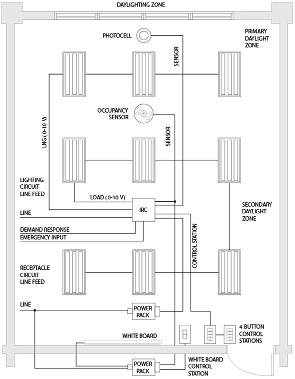
Leviton ceiling occupancy sensor wiring diagram. This video explains how to wire a leviton osc20 m0w occupancy sensor to a leviton integrated room controller irc. These state of the art devices use passive infrared ultrasonic or a combined multi sensing technology. Odc0s i1 wiring diagram with optional switch for override to off sensor switching relay. Wires routed through the threaded rod drop ceiling 1 thick maximum nut washer threaded rod 1 2 1 3 cm strip gage measure bare wire here step 3 5.
Mounting option diagram a occupancy sensor mounted to drop ceiling using threaded rod low voltage wires note. Occupancy sensor ceiling mounted multi technology 24vdc 30ma power exit connect gray wire for photocell ambient light hold off degree harmonic leviton occupancy sensors wiring diagram car diagrams source. Do not mount sensors closer than 10 feet from each other. Mounting option diagram a occupancy sensor mounted to drop ceiling using threaded rod low voltage wires note.
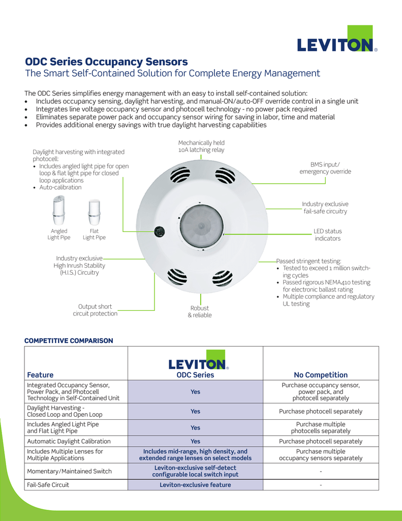
Occupancy sensor lighting control ceiling mounted 24vdc 10ma power consumption 1500 sq ft 360 degree major motion. Leviton offers a wide selection of occupancy sensors and vacancy sensors commonly referred to as motion sensors or motion detectors or motion light sensors for commercial and residential applications. Leviton offers a wide selection of ceiling mount occupancy sensors and vacancy sensors commonly referred to as motion sensors or motion detectors or motion light sensors for commercial and residential applications. Description odc0s i1 odc0s i2 odc0s i7 self contained ceiling mounted occupancy sensor switching.
Engineered to deliver a simple and cost e. Wires routed through the. Wires routed through the threaded rod drop ceiling 1 thick maximum nut washer threaded rod 1 2 1 3 cm strip gage measure bare wire here step 3 5. These state of the art devices use passive infrared ultrasonic or a combined multi sensing technology.
Sensors must be mounted on a vibration free surface. From wall and ceiling mount to wall switch and wireless leviton motion. Step 3 cont d mounting option diagram a occupancy sensor mounted to drop ceiling using threaded rod low voltage wires note. 120v black blue a blue b white white neutral s1 ordering information cat.
Dimensional diagram 2 15 54 6mm 4 3 109 2mm wiring diagrams odc0s i1 wiring diagram with optional switch for override to off same wiring for all voltages. Push the wires into the hole in the ceiling tile and insert the threaded rod until the. Push the wires into the hole in the ceiling tile and insert the threaded rod until the.

Leviton Ipv02 1lw Decora Vacancy Motion Sensor In Wall Switch Manual On 2 5a Single Pole White Dimmer Switches Amazon Com

Leviton Decora Manual On Occupancy Sensor Cableorganizer Com
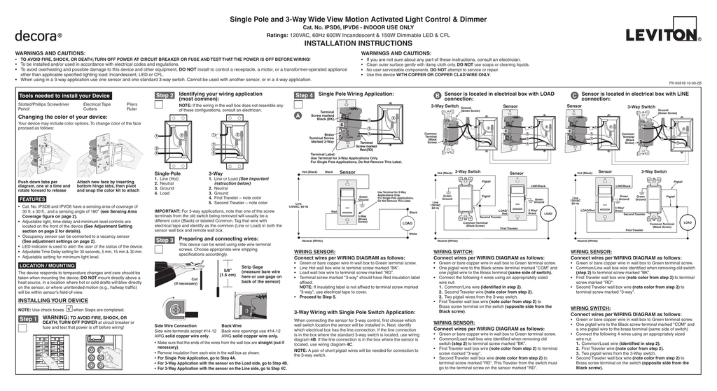
Leviton Decora Ipsd6 1lz Occupancy Sensor Installation Manualzz

Leviton Osfhu Itw Fixture Mounted Pir High Bay Sensor With 3 Interchangeable Lenses White By Leviton 45 54 From Leviton Motion Sensor Lights Outdoor Sensor
Leviton Decora 120 277 Volt Wall Switch Occupancy Sensor White 2 Pack P00 Ods10 1hw The Home Depot

Osc20 M0w

How To Install The Ipv02 Ipv05 Ips02 Ips05 Ips06 Universal Occupancy Vacancy Sensor Youtube
Leviton Decora Dual Relay Multi Technology Occupancy Sensor No Neutral White Ossmd Gdw The Home Depot
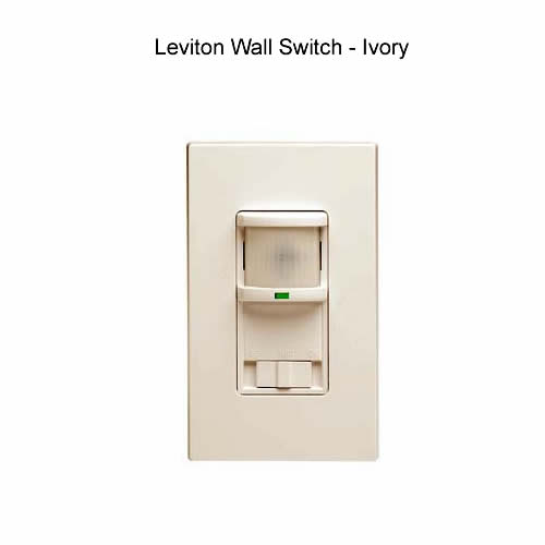
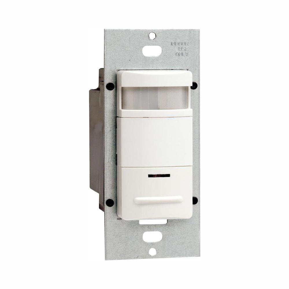
Leviton Wall Switch Pir Ocuppancy Sensor Lighting Controls

Leviton Irc How To Wire An Occupancy Sensor Youtube

Leviton Presents How To Install The Led Ceiling Occupancy Sensor Lampholder Youtube

Occupancy Sensor With Images Leviton Lighting Controls Locker Storage

Leviton Odc0s I1w Self Contained Ceiling Mount Occupancy Sensor And Switching Relay 1000 Watt 120v With Screwless Wallplates 10 Pack Amazon Com

Leviton Ips02 1lt Decora Motion Sensor In Wall Switch Auto On 2 5a Single Pole Light Almond Dimmer Switches Amazon Com

Makes Sense Building Sensors For Improved Energy Leviton Save Energy Green Business
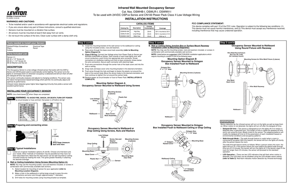
Infrared Wall Mounted Occupancy Sensor Installation
Leviton Fixture Mount Occupancy Sensor 1000 Sq Ft Passive Infrared White 6pfw2 Osfhp Itw Grainger

Leviton Ods10 Idt Decora 120 277v Wall Switch Occupancy Sensor Light Almond Motion Activated Wall Switches Amazon Com
Https Encrypted Tbn0 Gstatic Com Images Q Tbn 3aand9gct73nnhq Ja1plqkw9qagox5segsws8u2lo0ayqhbotqdor2ahr Usqp Cau
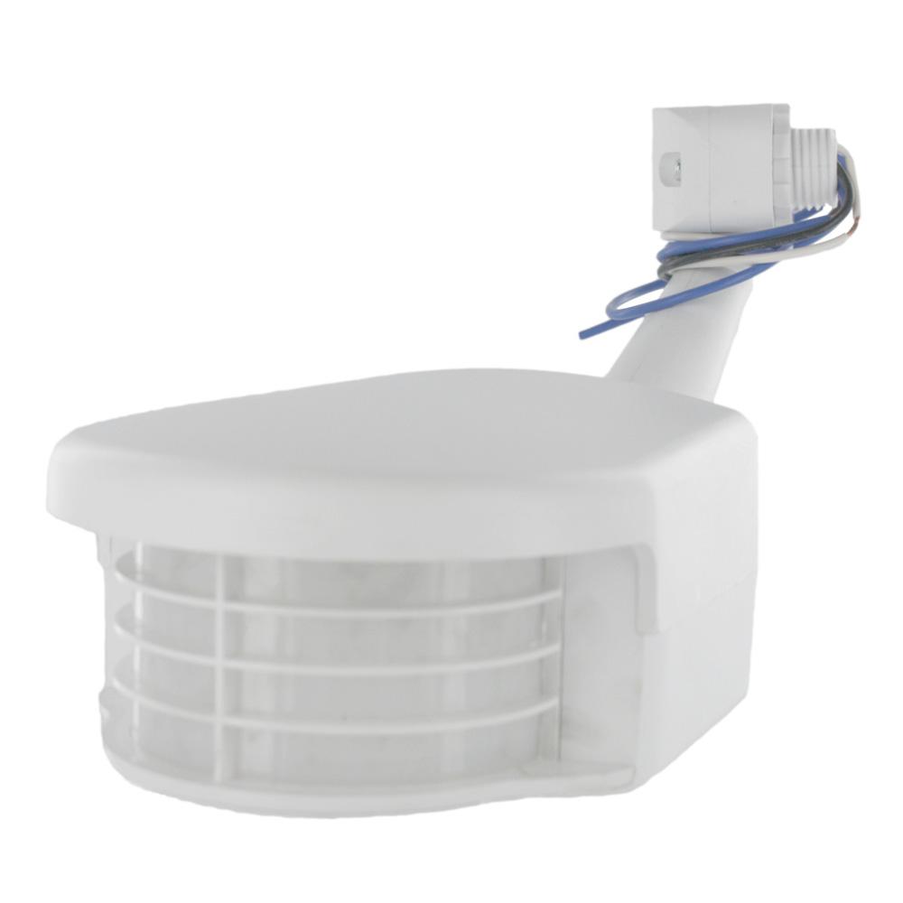
Leviton 120 Volt Residential Grade Passive Infrared 2500 Sq Ft 100 Outdoor Occupancy Sensor White Rs110 10w The Home Depot
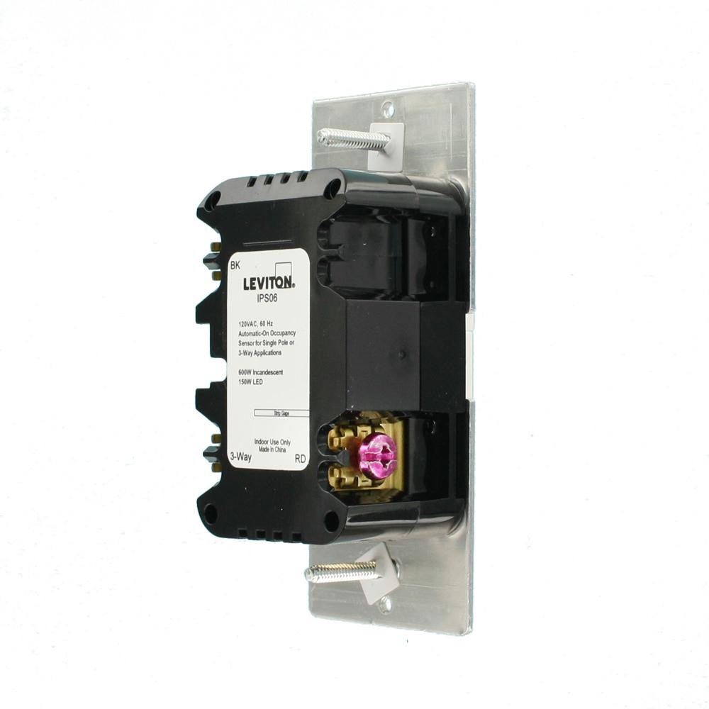
Leviton Decora Motion Sensor In Wall Switch Auto On 5 A Single Pole Or 3 Way White Ips06 1lw The Home Depot

Leviton Ods10 Ide Decora 120 277v Wall Switch Occupancy Sensor Black Amazon Com

Leviton Ips06 1lw Decora Motion Sensor In Wall Switch Auto On 5a Single Pole Or 3 Way White Dimmer Switches Amazon Com
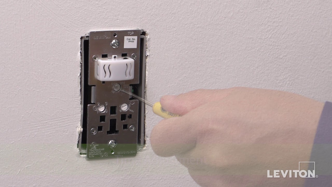
Leviton Presents How To Adjust The Settings On The Iphs5 Humidity Sensor Fan Control Youtube
Zoro

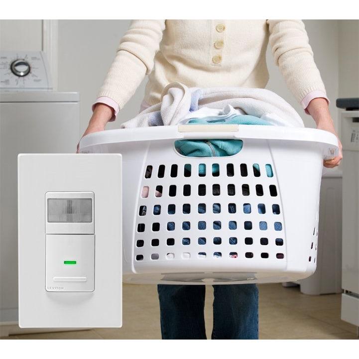
Leviton Decora Occupancy Sensor Wall Switch Led Nightlight

Leviton Odc Multi Tech Ceiling Occupancy Sensor

Leviton Ceiling Mount Occupancy Motion Sensor White In 2020 Leviton Motion Sensor Lights Outdoor Light Sensor

Leviton Ods10 Idi Decora Wall Switch Occupancy Sensor 10 Pack Ivory Amazon Com
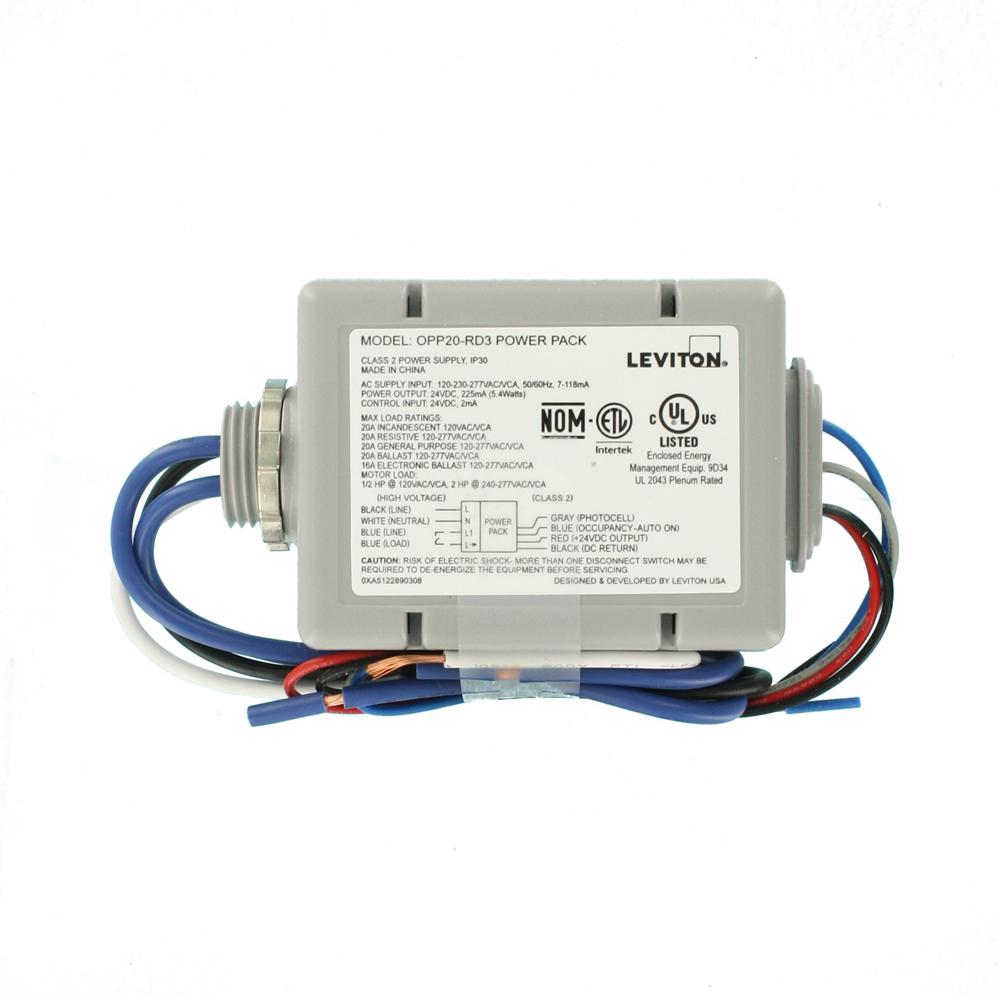
Leviton 20 Amp Power Pack For Occupancy Sensors Auto On Photocell Latching Relay Gray Opp20 Rd3 The Home Depot
Leviton Decora Motion Sensor In Wall Switch Auto On 2 5 A Single Pole Ivory R01 Ips02 1li The Home Depot

Amazon Com Leviton Opp20 D2 20 Amp Super Duty Power Pack For Occupancy Sensors Basic With Auto On Manual On And Local Switch Inputs Gray Home Improvement

Useful Usb Drive Design Usbank Usbdiskmobiles Usb Leviton Usb Chargers

Leviton Opp20 D2 20a Power Pack Occupancy Sensor Auto Manual On Local Switch Latching Relay Topbulb

Amazon Com Leviton 20 Amp Super Duty Power Pack For Occupancy Sensors Basic With Auto On Gray Home Improvement

Leviton Osfhu Itw High Bay Occupancy Sensor Leanlight

Parking Garage Control Basic
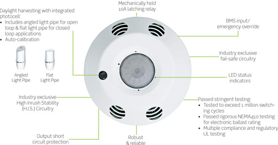
Diagram Ceiling Mount Occupancy Sensor Wiring Diagram Full Version Hd Quality Wiring Diagram Facediagram Belleilmersion Fr

Ods15 Idw

Zircon 68639 Leak Alert Plus Led Electronic Water Detector Leaks Led Detector
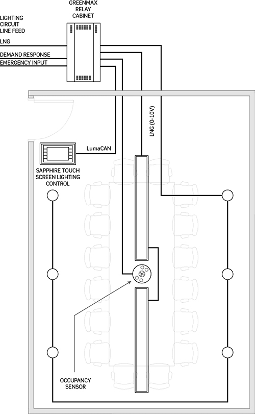
Greenmax Relay Control 2015 Leviton 2012 Iecc For Lighting Controls

Leviton Odc Pir Ceiling Vacancy Sensor
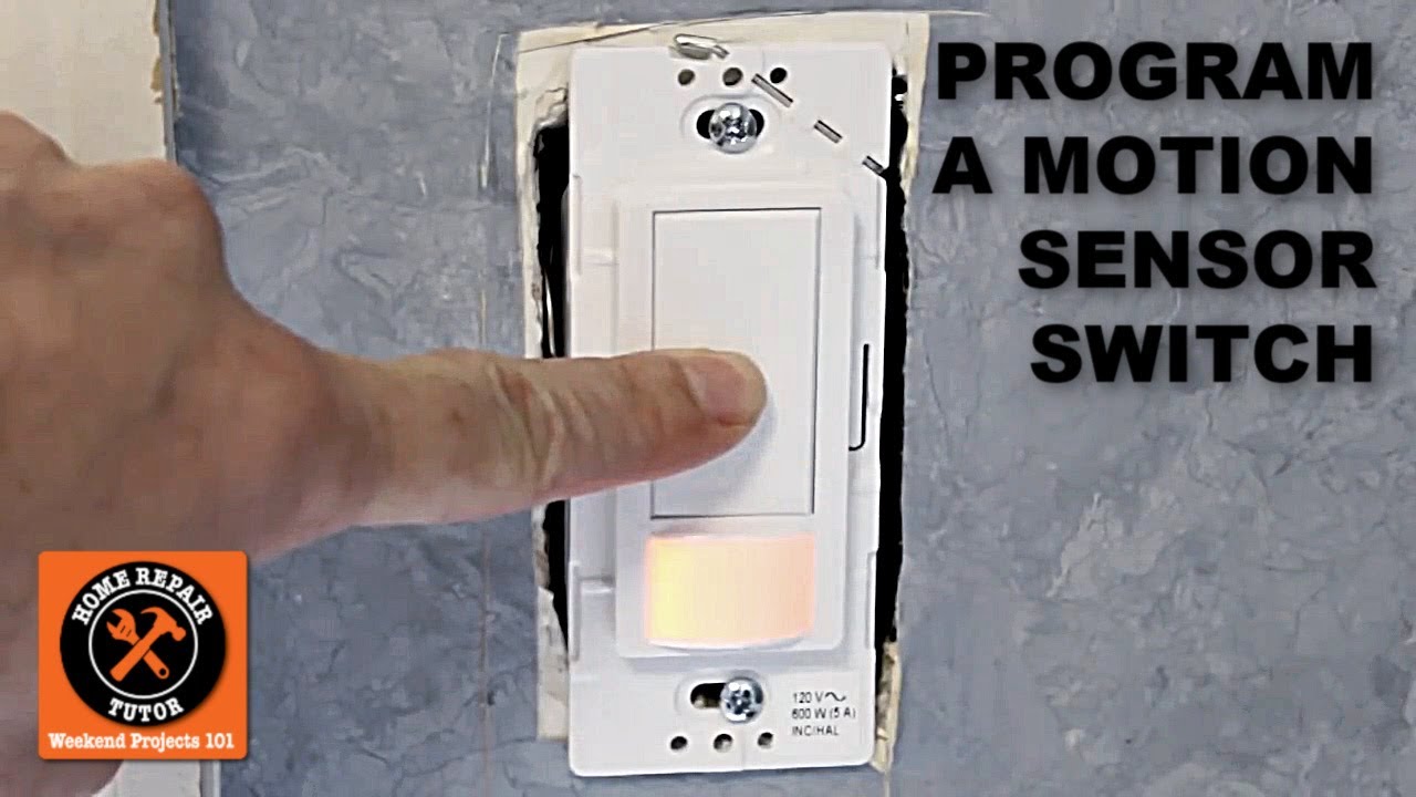
How To Program The Maestro Motion Sensor Light Switch Youtube